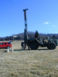
A soil resistivity meter is designed to test or measure
the electrical resistivity response for various depths of penetration. A soil resistivity instrument is often called an electrical resistivity meter or an earth resistance meter and can be rented for projects ranging from a few days to months. The resistivity meters are sized by their power rating, which determines if the equipment or instrument

can inject enough electrical current to geophysically investigate to the desired depths. In lower resistivity soils, low powered soil resistivity meters are capable of providing 10’s of milliamps while larger battery operated soil or earth resistivity meters are capable of providing 1000’s of milliamps of power, using 12 V deep cycle batteries or car batteries. The larger more sophisticated multi-electrode resistivity meters utilizing 84 or 112 probes are often programmed to automatically acquire 1000’s of soil resistivity measurements. Windmill generators are often grouped together, creating a windmill farm. These windmill farms can spread out over miles and require 100’s of soil resistivity measurements. Electrical engineers use the soil resistivity measurements to create a more energy efficient and safer design. The smaller soil resistivity instruments are intended for a few measurements with 2, 3, or 4 pins.

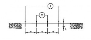
Common arrays for all types of soil resistivity testing methods
include Wenner, Schlumberger, and Dipole Dipole. There are many other geometries available. The geometry of the array, somewhat, controls how current flows and electrical potentials are measured. The path of the actual current flow can be a complex path that is dependent on subsurface materials and, sometimes, cultural interference. Cultural interference (e.g. metal, leakage from power lines, or unexpected pore fluids) can complicate the interpretation of the soil resistivity results.
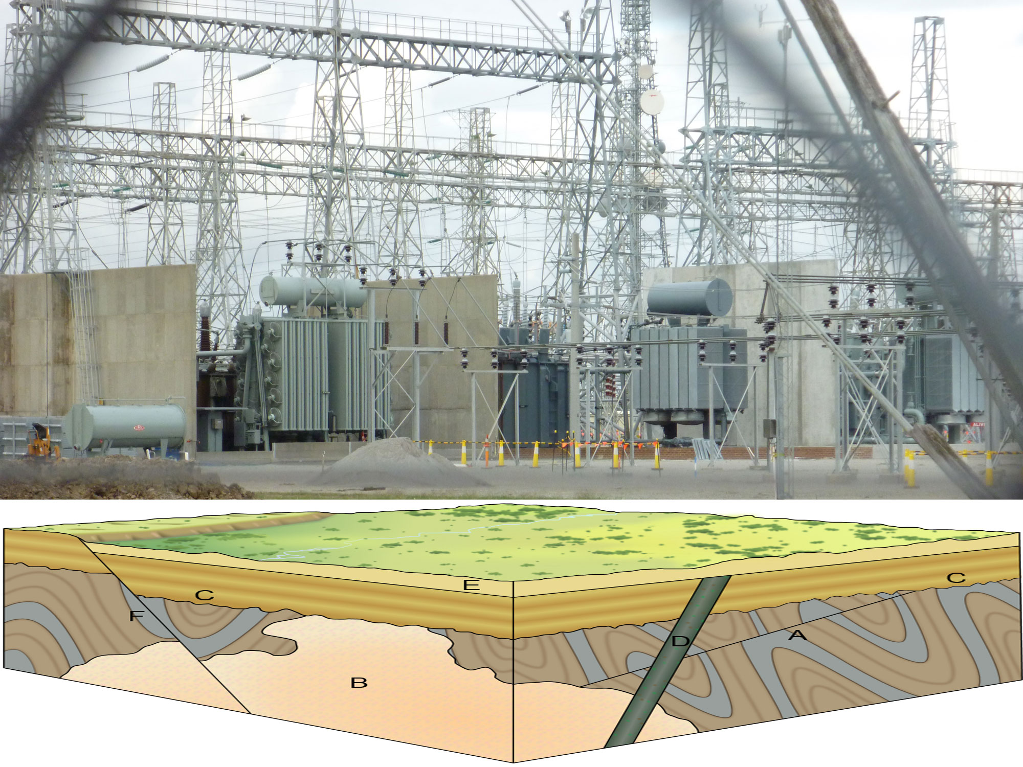
Electrical engineers at power plants, substations, and terminals
may use a different set of techniques then geophysicists use to characterize the local geology. Clearly a large power plant requires far more soil resistivity values to design a facility than a small manufacturing plant. Characterizing the geology and associated subsurface conditions is a second application that soil or earth resistivity meters are used. In geophysical investigations, the earth resistivity meter can be used to assess pore fluid resistivities and the electrical resistivity of various rocks or bedrock units. Characterizing geologic conditions at depth can be challenging with smaller earth resistivity meters that do not have memory.

As seen at the top of the page, there is a page on electrical engineering applications and a page dedicated towards geology and geophysics.

For more information send us an email.


43 thoughts on “Soil Resistivity Meter Rental for Geophysics, Electrical Engineering, and Geology”
I have read about the SuperSting, how many models are there?
AGI has other earth resistivity meters in addition to the SuperSting. The SuperSting comes with the ability to record 1 or 8 resistivity measurements at one time; thus, called a R1 or R8. After that there is a value that indicates how many electrodes it is or was setup up to address, usually 28, 56, 64, 84, or 112. But understand, switch boxes can be combined or “daisy chained” together for as large of a system you want.
I have a farm field and I want to measure the soil resistivities right at the surface. What can I use?
If you mean the soil you can grab at the surface, you could try a electrical resistivity soil box. However, many farmers want to electrically characterize an entire field or 1000’s of acres. In these cases, they often use a Geonics EM-38 with GPS. It is a soil terrain conductivity meter that measures variations in apparent soil conductivity, which is the inverse of apparent resistivity. It can measure from the surface to a few feet. The biggest problem is building a cart made without any metal and then pulling across the field. The GPS does a great job keeping track of where you went.
Where can I get a electrical resistivity soil box and meter?
A Megger soil resistivity meter can be rented and a soil resistivity box is not too difficult to build. There is an ASTM G57 document that explains how to build and use a soil box resistivity box.
Is a 3-D electrical resistivity survey more accurate than a 1-D or 2-D resistivity survey?
On paper an earth resistivity survey using 3-D geophysical methods should be the most accurate; however, it is often expensive and difficult to get the coverage and volume of data. Closely spaced 2-D lines in areas that do not change too rapidly may be a cost effective solution. As with most geophysical technology, I am sure the equipment will improve. I think it is a case where the geophysical instrumentation is still trying to catch up to the geophysical theory. It wasn’t too long ago that 1-D electrical resistivity soundings were the only resistivity method customers could afford.
How bad are lightning storms during a test.
AGI makes it clear in the SuperSting manual that “Do not operate during an approaching thunderstorm. Thunderstorms are dangerous both for you and the equipment. The instrumentation contains sensitive CMOS circuitry and can be destroyed by nearby lightning. For your own safety it is not a good idea to stand at the end of a long conductive cable during a thunderstorm.”
In addition to ligntning, people need to think about explosions. While for most people it is obvious that during a survey you should not touch the cables or electrodes that are connected to a soil resistivity meter. It may be less obvious to operators that it is not safe to operate in an area that has explosive gases.
How much juice does a SuperSting have?
I would not be to quick to test if this equipment can harm you. Without thinking, I have zapped myself more than once. But once again, AGI is quick to point out that “Since the geophysical resistivity method implies that an electric current is transmitted into the ground, it is necessary to use electrically energized ground stakes (up to 400 V using the internal transmitter, up to 3,000 V using the PowerSting external transmitter). It is therefore absolutely necessary that the survey line with its ground stakes and connections be monitored for the duration of the survey so that people, children and animals do not touch the electrode stakes.” Stay safe.
I AM A CONSULTING ENGINEER, RETAINED TO LOCATE A WATER MAIN LEAK SERVING A LARGE(70-UNIT) MOBILE HOME PARK, WITH INDIVIDUAL CURB STOPS FOR EACH MOBILE HOME UNIT. THE MAIN RUNS IN A LONG LOOP AROUND THE MOBILE HOME PARK—PROBABLY ABOUT A MILE IN TOTAL LENGTH
I HAVE ESTIMATED THE LOCAL WATER TABLE TO BE AT LEAST TWO FEET LOWER THAN THE SETTING DEPTH OF THE WATER MAIN, WHICH IS PROBABLY ABOUT 5-FEET BELOW THE SURFACE.
DO YOU THINK A SOIL RESISTIVITY SURVEY MAY REVEAL THE GENERAL LOCATION OF THE LEAK, BY VIRTUE OF THE ADDED SOIL M0ISTURE RESULTING FROM THE LEAK
I need a soil resistivity meter to rent in Ghana for a few days. Starting 16th October, 2013.
( Soil resistivity measurement in order to find the exact point where magnesium anode shall be buried)
Thanks
I think that given that your geophysical investigation is not very far off, you should see if the manufacture has a soil resistivity meter or a representative overseas.
I just finished a resistivity survey to locate a buried metal septic tank in clays. I am not sure is worked very well. Any ideas.
If you are looking for metal, I would use a magnetometer (if you have iron) and a Geonics EM-31 or Geonics EM61. I don’t think you will get very good penetration with ground penetrating radar GPR in clays. While the Geonics EM-61 is designed to locate buried metal, the Geonics EM31 is a terrain conductivity meter that is sensitive to buried metal.
We have a large 100+ acre site with issues. I’m think of using resistivity to find variations across the site. We have 25 to 50 feet of soils over granite. What are the pros and cons of resistivity profiling and 2-D electrical resistivity imaging?
Wow, a geophysical question like that electrical resistivity question could make a new page on SoilResistivityMeter.com. This response won’t cover everything but it is a start. First of all, earth resistivity surveys along the surface (different then borehole resistivity) are done as profiles, 1-D soundings, 2-D resistivity cross sections, or 3-D resistivity images. A true 3-D survey is not the same as conducting parallel 2-D resistivity cross sections and creating a 3-D representation. A true 3-D survey can be fairly expensive and is difficult to configure for very large areas. I lean towards electrical resistivity profiling and 2-D resistivity images. Soil resistivity profiling often covers a large area using a single resistivity method (e.g. Wenner, Schlumberger, or Dipole-Dipole) with a fixed array, configured for the primary depth of concern. The data is collected and used to create a contour plot of apparent resistivity in plan view. This method works well for mapping lateral variations across a site. Once an area of interest is found then detailed cross sections of electrical resistivity are acquired using a multi-electrode resistivity system. These electrical resistivity cross sections are created from 1000’s of measurements along the line. Resistivity profiling yields more of a qualitative analysis and can be time consuming using a soil resistivity meter (earth resistivity meter). On the other hand, a Geometrics OhmMapper capacitance coupled resistivity meter or a Geonics EM31 or Geonics EM-34 can acquire far more readings in a short period of time. The Geonics instruments measure apparent conductivity, which is the inverse of apparent resistivity. The Geonics EM-31 penetrates to a maximum depth of roughly 20 ft, while the Geonics EM34 is capable of depths to roughly 200 feet and slower going. An EM34 survey may not be a good choice if the soils are electrically resistive. In this case, a Geometrics OhmMapper may be the best route because it collects data very quickly, approximately a reading per second, and is capable of the depths of penetration you are looking to achieve. This is a basic summary and further details are outside the scope of this comment, for now. Watch for a new page on SoilResistivityMeter.com
I have a pump and treat facility operating on a property. It is cleaning up the groundwater. The contaminate is very conductive. Is electrical resistivity a good choice for monitoring if the program is working?
Maybe. It depends on what you mean by working and how big of a change in electrical resistivity you expect. Earth resistivity is not a crystal ball but it is sensitive to changes in pore fluid resistivity. Assuming the treating process decreases the pore fluid resistivity and the groundwater isn’t too deep, electrical resistivity measurements may be a good choice. I am sure there are time-lapse surveys being done as we speak. They take earth resistivity measurements at various time intervals and document the changes in apparent resistivity. To avoid problems with changing site conditions, some of these programs have permanently buried electrodes. If the zone of interest is less than 10’s of feet deep, you may want to consider an OhmMapper resistivity survey or possibly a Geonics EM-31 survey over the entire site. This would be ideal in an open field. The apparent conductivity data from the Geonics EM31 or the resistivity data acquired from the OhmMapper survey using closely spaced parallel lines could be used to create a resistivity map in plan view. Once you confirm that changes in soil resistivity or apparent conductivity correlate with your sampling program, you could repeat the geophysical survey as often as needed to characterize changes as a function of time. Be aware that varying the cone of depression around any wells may impact the resistivity results and lead to undesirable geophysical results.
Trying to decide between a dipole dipole survey and a Wenner array type survey. What do you think?
Based on sensitivity curves, there is some consensous that a Wenner array is likely better for mapping flat or layer type features; whereas, dipole dipole resistivity methods are better at imaging lateral changes (e.g. a dyke). If you are doing a multi-electrode resistivity survey with a SuperSting R8 you will find that it takes less time to conduct a dipole-dipole survey then a Wenner survey. Only one reading can be taken at a time with a Wenner array. In comparison, eight resistivity measurements can be acquired at one time with an R8.
For what I do my Megger soil resistivity meter provides enough power. I am working at a substation and I am getting bad results. What will happen if I hook my other Megger together.
I wouldn’t hook two soil resistivity meters together unless they are designed for it. Besides other issues, soil resistivity meters are typically AC. You can imaging what might happen. You are better off renting a larger earth resistivity meter.
I am in Africa and I need to measure soil resistivities to 300m or 500m. What else can I use?
Soil resistivity measurements to those depths can be tough and imply you are looking for some very large features. Electrical resistivity soundings are not out of the question but challenging. A time domain electromagnetic survey, TDEM, with Geonics Protem receive and a Geonics TEM57-MK2 Transmitter or Geonics TEM67 Transmitter may be a more practical way of going. While the TEM47 is smaller and portable, it is not designed to reach the depths of penetration you mentioned. The Geonics TEM57 transmitter is designed for 200 to 500 meters and the TEM67 is for a 1000 meters or more. The Geonics TEM67 may be more than you need but can be used as a TEM57 or the more powerful TEM67, if the power module and generator is used. As Geonics puts it a “Time Domain Systems: provide measurement of vertical subsurface conductivity for definition of the conductivity / resistivity profile and / or detection of geologic anomalies within an exploration range of 5 m (for environmental / engineering applications) to greater than 1000 m (for deep resource exploration).”
Will I get the same results as an soil resistivity meter?
Electromagnetic methods and electrical resistivity methods often depend on inverse modeling to yield a representation of the subsurface. The solutions are not unique and are dependent on the complexities of the local geology and the resolution requirements of you survey. I would hope you would yield nearly the same interpretation using both geophysical methods but there are factors that complicate giving you a yes or no answer. You need to do some preemptive modeling to determine how the geophysical instruments may respond to your site conditions.
How close to a building can I get?
There are many factors. If you know where there are underground facilities it can help. For a resistivity test using a 4 pin Wenner array, one rule of thumb is to be greater than 1/2 the “A” space or 1/6th the length of the Wenner array. More is better and being perpendicular to any pipe, wire, cable, etc. is even better.
I need to take resistance tests for troubleshooting. I want to leave the electrodes in the ground because different ground configurations are being tested. What problems will I have?
Other than having someone hurt themselves or damage equipment on the resistivity probes, the electrodes should be fine. Depending on the soils and the type of metal you use for the electrodes there may be a problem with corrosion. Customers often use stainless steel because it doesn’t rust. Also, you want make sure there clean and have somewhat of a polished appearance. As a side note, ASTM G57 says 5.1.4 Electrodes fabricated from mild steel or martensitic stainless steel 0.475 to 0.635 cm (3⁄16 to 1⁄4 in.) in diameter and 30 to 60 cm (1 to 2 ft) in length are satisfactory for most field measurements. Both materials may require heat treatment so that they are sufficiently rigid to be inserted in dry or gravel soils. The electrodes should be formed with a handle and a terminal for wire attachment.
I conducted an earth resistivity survey years ago. An associate used a sting multielectrode system with active electrodes. Back then he had problems and I don’t know enough about it to say if it was the active electrodes or operator error. I want to do another resistivity survey and think I will use the passive electrodes. Do they work?
AGI’s SuperSting R8 with passive electrodes has worked very well for me. The passive system is hardwired and the electrodes are addressed using a switch box. The resistivity meter or console is programed to turn on and turn off the electrodes through the switch box. Other than operator error, this system fails, more or less, only when wires, switches, or other hardware is damaged. In contrast, active electrodes are programmed. If they are incorrectly programed or lose their programing, you can have problems, in addition to hardware failures that can occur with a passive system.
I think I will try the SuperSting with the passive electrode system.
I am hired to do a SP at a leaky dam. Where can I get some electrodes? I have a good voltmeter that reads millivolts.
You may want to buy a couple of non-polarizable (porous pots) electrodes for the self potential measurements. If you decide to shop around, induced polarization IP surveys use the same type of electrical resistivity probe.
I need a soil resistivity meter. What should I rent?
Why are you measuring the soil resistivity?
Ground rods for a factory.
A smaller soil resistivity meter is often used. A larger resistivity meter will cost a little more to rent and you won’t have to worry about if you have enough power.
Comments are closed.