A soil resistivity meter used at a
power plant, substation, or terminal
generally utilizes large electrical resistivity arrays. In extreme conditions, the electrode spacing or probe spacing may be 1000’s of feet, depending on the electrical engineer’s application. Once again, these great distances may require a more powerful resistivity meter than what can be supplied by a smaller soil resistivity meter. Before a power plant, substation, or terminal is updated or built, electrical engineers characterize the soil resistivities and analyze the grounding system for its capacity. While electromagnetic methods are also used in engineering geophysics to determine resistivities by measuring apparent conductivity (the inverse of apparent resistivity), soundings with a resistivity meter are often acquired using a Wenner or Schlumberger 4 probe array to characterize the unit resistivities of the soils and rock at depth. Unit resistivities represent the electrical resistance of a formation or geologic unit.

At times, the field data from the resistivity meter is plotted and used in its most basic format. In other instances, a more demanding analysis requiring curve matching or computer models may be needed to assist with determining the unit resistivities. An electrical engineer then use the unit resistivities to assist with designing the grounding system. At existing substations, terminals, or power plants, the previous design does not always allow for the expansion or for the addition of new equipment. For sites that have existing ground systems, which are normally very large, the capacity of the designed ground system can be evaluated using other resistivity methods, such as, fall of potential, intersecting curves, star delta, and slope. These resistivity methods assist with determining if the facility has a sufficiently low ground resistance to avoid high voltages and unsafe site conditions.
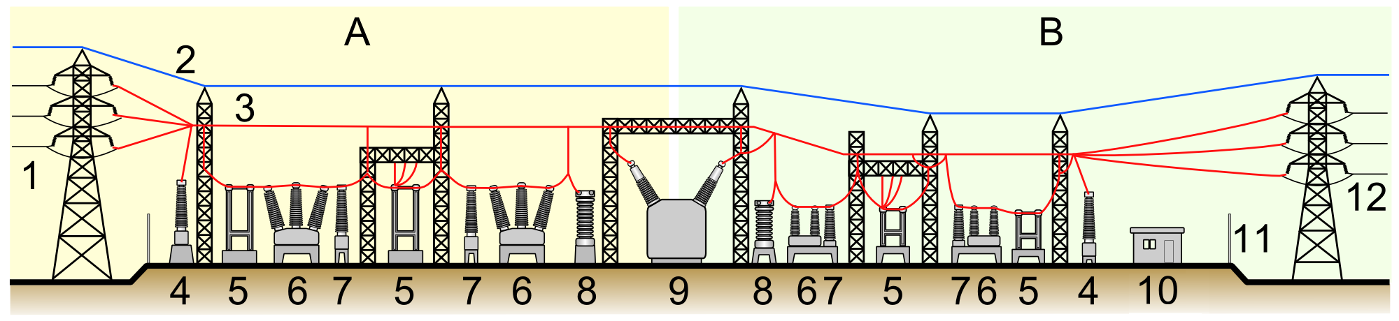
Looking at the anatomy of terminal substation provides an indication of how many places the ground system is depended on.Complexities of a substation are shown in the model. The model shows on side A the Primary power lines and on side B the Secondary power lines. In between one sees the 1.Primary power lines, 2.Ground wire, 3.Overhead lines, 4.Transformer for measurement of electric voltage, 5.Disconnect switch, 6.Circuit breaker, 7.Current transformer, 8.Lightning arrester, 9.Main transformer, 10.Control building, 11.Security fence, and 12.Secondary power lines. Soil resistivities play an important part in the construction of a substation and the associated power lines.